
接着上一篇planning模块-路径边界 障碍物 继续介绍.当IsIrrelevantObstacle函数返回false时,说明当前障碍物影响到了参考线.
BuildReferenceLineStBoundary函数
mutable_obstacle->BuildReferenceLineStBoundary(reference_line_,
                                          adc_sl_boundary_.start_s());
adc_sl_boundary_:是在ReferenceLineInfo::Init函数中构造的
bool ReferenceLineInfo::Init(const std::vector<const Obstacle*>& obstacles,
                             double target_speed) {
  const auto& param = VehicleConfigHelper::GetConfig().vehicle_param();
  // stitching point
  const auto& path_point = adc_planning_point_.path_point();
  Vec2d position(path_point.x(), path_point.y());
  Vec2d vec_to_center(
      (param.front_edge_to_center() - param.back_edge_to_center()) / 2.0,
      (param.left_edge_to_center() - param.right_edge_to_center()) / 2.0);
  Vec2d center(position + vec_to_center.rotate(path_point.theta()));
  Box2d box(center, path_point.theta(), param.length(), param.width());
	...
if (!reference_line_.GetSLBoundary(box, &adc_sl_boundary_)) {
    AERROR << "Failed to get ADC boundary from box: " << box.DebugString();
    return false;
  }
param:是从/home/zsy/apollo/modules/common/data/vehicle_param.pb.txt文件中获取的配置
adc_planning_point_:是规划起点
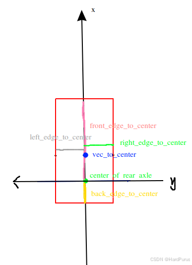
需要解释一下,从上面配置中获取到的front_edge_to_center/back_edge_to_center/left_edge_to_center/right_edge_to_center的参数是在自车坐标系下的,自车坐标系是以后轴中心为原点,也就是下图绿色原点,y轴左正右负,x轴上正下负.
vec_to_center:获取的就是自车坐标系下的车体中心坐标
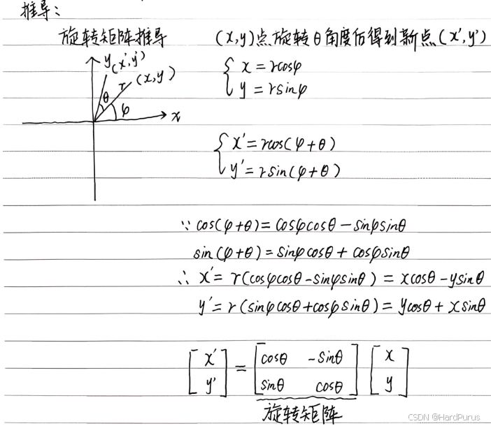
vec_to_center.rotate(path_point.theta())
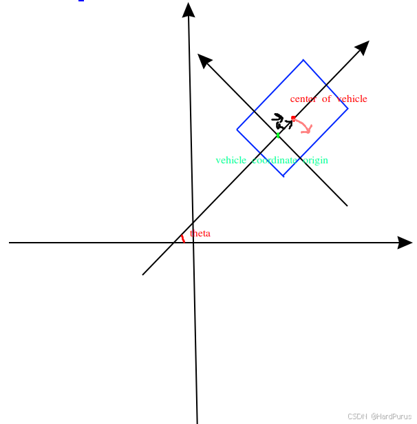
vec_to_center是自车坐标系下的几何中心坐标,path_point.theta()是笛卡尔坐标系下的自车方向角,调用rotate其实就是将\vec{a}旋转\theta角度,\vec{a}的大小其实是几何中心与自车坐标系原点的偏移量,旋转一个方向角后,这个偏移量就从自车坐标系下的偏移量变为了笛卡尔坐标系下的偏移量,而自车原点也就是后轴中心在笛卡尔坐标系下的坐标是position
Vec2d center(position + vec_to_center.rotate(path_point.theta()));
那么center就是自车几何中心点在笛卡尔坐标系下的坐标了.rotate的实现就是用旋转矩阵乘以vec_to_center.
Box2d box(center, path_point.theta(), param.length(), param.width());
构建box
Box2d::Box2d(const Vec2d ¢er, const double heading, const double length,
const double width)
: center_(center),
length_(length),
width_(width),
half_length_(length / 2.0),
half_width_(width / 2.0),
heading_(heading),
cos_heading_(cos(heading)),
sin_heading_(sin(heading)) {
CHECK_GT(length_, -kMathEpsilon);
CHECK_GT(width_, -kMathEpsilon);
InitCorners();
}
void Box2d::InitCorners() {
  const double dx1 = cos_heading_ * half_length_;
  const double dy1 = sin_heading_ * half_length_;
  const double dx2 = sin_heading_ * half_width_;
  const double dy2 = -cos_heading_ * half_width_;
  corners_.clear();
  corners_.emplace_back(center_.x() + dx1 + dx2, center_.y() + dy1 + dy2);
  corners_.emplace_back(center_.x() + dx1 - dx2, center_.y() + dy1 - dy2);
  corners_.emplace_back(center_.x() - dx1 - dx2, center_.y() - dy1 - dy2);
  corners_.emplace_back(center_.x() - dx1 + dx2, center_.y() - dy1 + dy2);

}
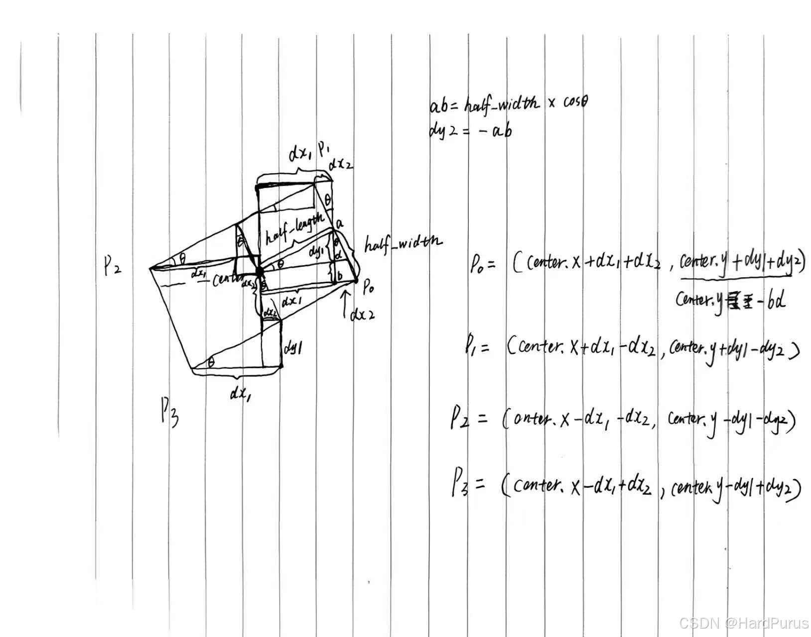
构建角点
  for (auto &corner : corners_) {
    max_x_ = std::fmax(corner.x(), max_x_);
    min_x_ = std::fmin(corner.x(), min_x_);
    max_y_ = std::fmax(corner.y(), max_y_);
    min_y_ = std::fmin(corner.y(), min_y_);
  }
构建笛卡尔坐标系下的AABB矩形
reference_line_.GetSLBoundary(box, &adc_sl_boundary_)
adc_sl_boundary_:是获取的自车在frenet坐标系下的AABB矩形,GetSLBoundary在上一篇planning模块-路径边界 障碍物 已经介绍过.
现在回到
mutable_obstacle->BuildReferenceLineStBoundary(reference_line_,adc_sl_boundary_.start_s());
reference_line_:是参考线
adc_sl_boundary_.start_s():是自车在frenet坐标系下的车身最后边缘的纵向距离
if (is_static_ || trajectory_.trajectory_point().empty()) {
    std::vector<std::pair<STPoint, STPoint>> point_pairs;
    double start_s = sl_boundary_.start_s();
    double end_s = sl_boundary_.end_s();
    if (end_s - start_s < kStBoundaryDeltaS) {
      end_s = start_s + kStBoundaryDeltaS;
    }
    if (!reference_line.IsBlockRoad(perception_bounding_box_, half_adc_width)) {
      return;
    }
    point_pairs.emplace_back(STPoint(start_s - adc_start_s, 0.0),
                             STPoint(end_s - adc_start_s, 0.0));
    point_pairs.emplace_back(STPoint(start_s - adc_start_s, FLAGS_st_max_t),
                             STPoint(end_s - adc_start_s, FLAGS_st_max_t));
    reference_line_st_boundary_ = STBoundary(point_pairs);
  }
当障碍物是静态障碍物或障碍物没有预测轨迹线时执行上面逻辑
IsBlockRoad函数
perception_bounding_box_:
perception_bounding_box_({perception_obstacle_.position().x(),
                                perception_obstacle_.position().y()},
                               perception_obstacle_.theta(),
                               perception_obstacle_.length(),
                               perception_obstacle_.width())
half_adc_width:自车宽度的一半
OverlapWith函数
const Vec2d center = box.center();
障碍物的几何中心点坐标
const double radius_sqr = Sqr(box.diagonal() / 2.0 + width) + kMathEpsilon;
box.diagonal() / 2:障碍物外接圆的半径
box.diagonal() / 2.0 + width:在把半径向外扩半个车宽
Sqr(box.diagonal() / 2.0 + width):变成半径平方
+kMathEpsilon:数值稳定性,防止浮点误差
if (segment.DistanceSquareTo(center) > radius_sqr) {
      continue;
    }
判断粗糙参考线中segment到障碍物box中心点的最小距离平方如果大于扩展后外接圆半径的平方radius_sqr,说明这条线段不可能碰到box
if (box.DistanceTo(segment) <= width + kMathEpsilon) {
      return true;
    }
Box2d::DistanceTo(const LineSegment2d &line_segment)函数
if (line_segment.length() <= kMathEpsilon) {
    return DistanceTo(line_segment.start());
  }
double Box2d::DistanceTo(const Vec2d &point) const {
  const double x0 = point.x() - center_.x();
  const double y0 = point.y() - center_.y();
  const double dx =
      std::abs(x0 * cos_heading_ + y0 * sin_heading_) - half_length_;
  const double dy =
      std::abs(x0 * sin_heading_ - y0 * cos_heading_) - half_width_;
  if (dx <= 0.0) {
    return std::max(0.0, dy);
  }
  if (dy <= 0.0) {
    return dx;
  }
  return hypot(dx, dy);
}
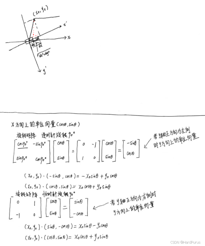
  const double dx =
      std::abs(x0 * cos_heading_ + y0 * sin_heading_) - half_length_;
在{x}'方向上投影长度的绝对值减去半个车长,剩余长度用于判断segment起点在{x}'方向上,是在矩形内还是矩形外,小于等于0说明在矩形边上或矩形内,直接用dy表示segment起点到矩形几何中点的距离
std::abs(x0 * sin_heading_ - y0 * cos_heading_) - half_width_;
在{y}'方向上投影长度的绝对值减去半个车宽,剩余长度用于判断segment起点在{y}'方向上,是在矩形内还是矩形外,小于等于0说明在矩形边上或矩形内,直接用dx表示segment起点到矩形几何中点的距离
hypot(dx, dy)
如果dx和dy都大于0,表示segment的起点在矩形外,则计算dx,dy的欧几里德距离,也可以理解为角点到segment起点的距离
当line_segment.length()不是极小值时,会通过下面方式计算line_segment到box的距离
  const double ref_x1 = line_segment.start().x() - center_.x();
  const double ref_y1 = line_segment.start().y() - center_.y();
  double x1 = ref_x1 * cos_heading_ + ref_y1 * sin_heading_;
  double y1 = ref_x1 * sin_heading_ - ref_y1 * cos_heading_;
  double box_x = half_length_;
  double box_y = half_width_;
  int gx1 = (x1 >= box_x ? 1 : (x1 <= -box_x ? -1 : 0));
  int gy1 = (y1 >= box_y ? 1 : (y1 <= -box_y ? -1 : 0));
  if (gx1 == 0 && gy1 == 0) {
    return 0.0;
  }
计算line_segment的起点是在box内还是外
const double ref_x2 = line_segment.end().x() - center_.x();
  const double ref_y2 = line_segment.end().y() - center_.y();
  double x2 = ref_x2 * cos_heading_ + ref_y2 * sin_heading_;
  double y2 = ref_x2 * sin_heading_ - ref_y2 * cos_heading_;
  int gx2 = (x2 >= box_x ? 1 : (x2 <= -box_x ? -1 : 0));
  int gy2 = (y2 >= box_y ? 1 : (y2 <= -box_y ? -1 : 0));
  if (gx2 == 0 && gy2 == 0) {
    return 0.0;
  }
计算line_segment的结束点是在box内还是外
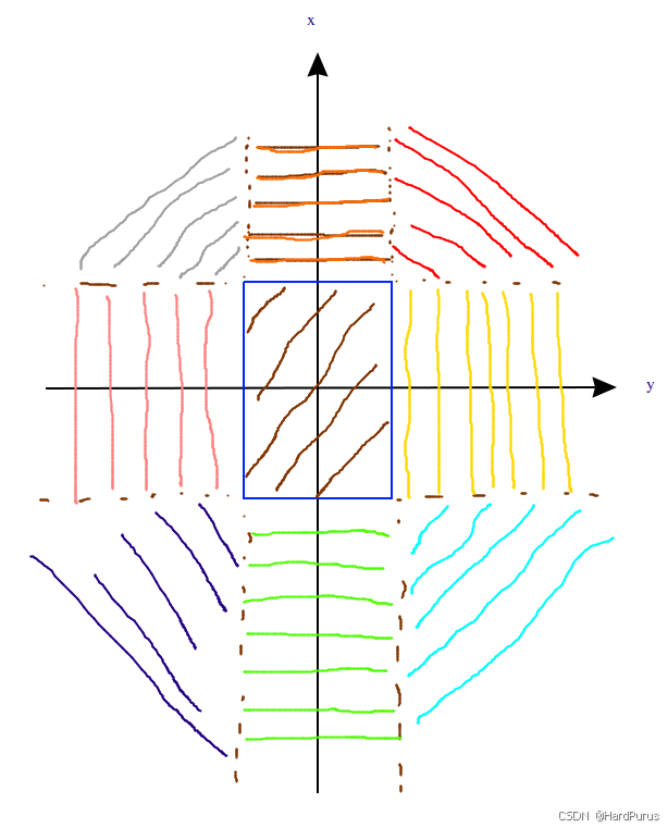
1:点在矩形边界外(正向)
-1:点在矩形边界外(负向)
0:点在矩形的宽度或长度范围内
gx/gy组合后就是9个区域
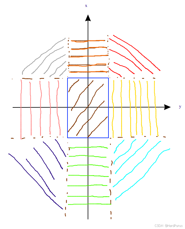
| (gx, gy) | 真实物理位置 |
|---|---|
| (0,0) | 车身内部 |
| (1,0) | 车头正前 |
| (-1,0) | 车尾正后 |
| (0,1) | 车右侧并排 |
| (0,-1) | 车左侧并排 |
| (1,1) | 车头右前 |
| (1,-1) | 车头左前 |
| (-1,1) | 车尾右后 |
| (-1,-1) | 车尾左后 |
if (gx1 < 0 || (gx1==0 && gx2<0)) { ... }
if (gy1 < 0 || (gy1==0 && gy2<0)) { ... }
目的:
保证至少一端在 x ≥ 0(前方)
保证至少一端在 y ≥ 0(右侧)
原理:凸形状 + 对称性
Box 是对称矩形
距离计算对称性:后方点和左侧点的距离,可以通过镜像变换到前方右侧计算
这样可以把“后方/左侧”线段转化为“前方/右侧”处理,数学上是等价的
依据:矩形对称 + 欧几里得距离不变性(镜像不会改变最短距离)
if (gx1 < gy1 || (gx1==gy1 && gx2 < gy2)) { swap(...) }
目的:
统一突出轴为 x 方向(x ≥ y ≥ 0)
原理:计算 Box-角/边最短距离时,总是以主轴突出方向为参考
这样:
不用分别考虑 x 突出还是 y 突出的情况
算法复杂度降低,只有一套公式即可
依据:凸矩形 + 欧几里得距离,凸函数最小值总出现在角或边的端点,交换轴不会改变距离最小值,只是把问题标准化
if (gx1 == 1 && gy1 == 1)
起点在 Box 前右角外侧,也就是上图红色区域,线段终点可能在不同位置
gx2 * 3 + gy2
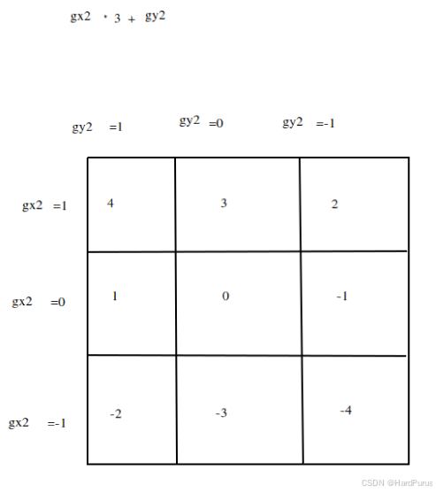
本质是将gx2和gy2的9种组合可以通过一个表达式表示,这样就可以通过switch语句进行选择进入哪个case,进入的case就是终点的位置.
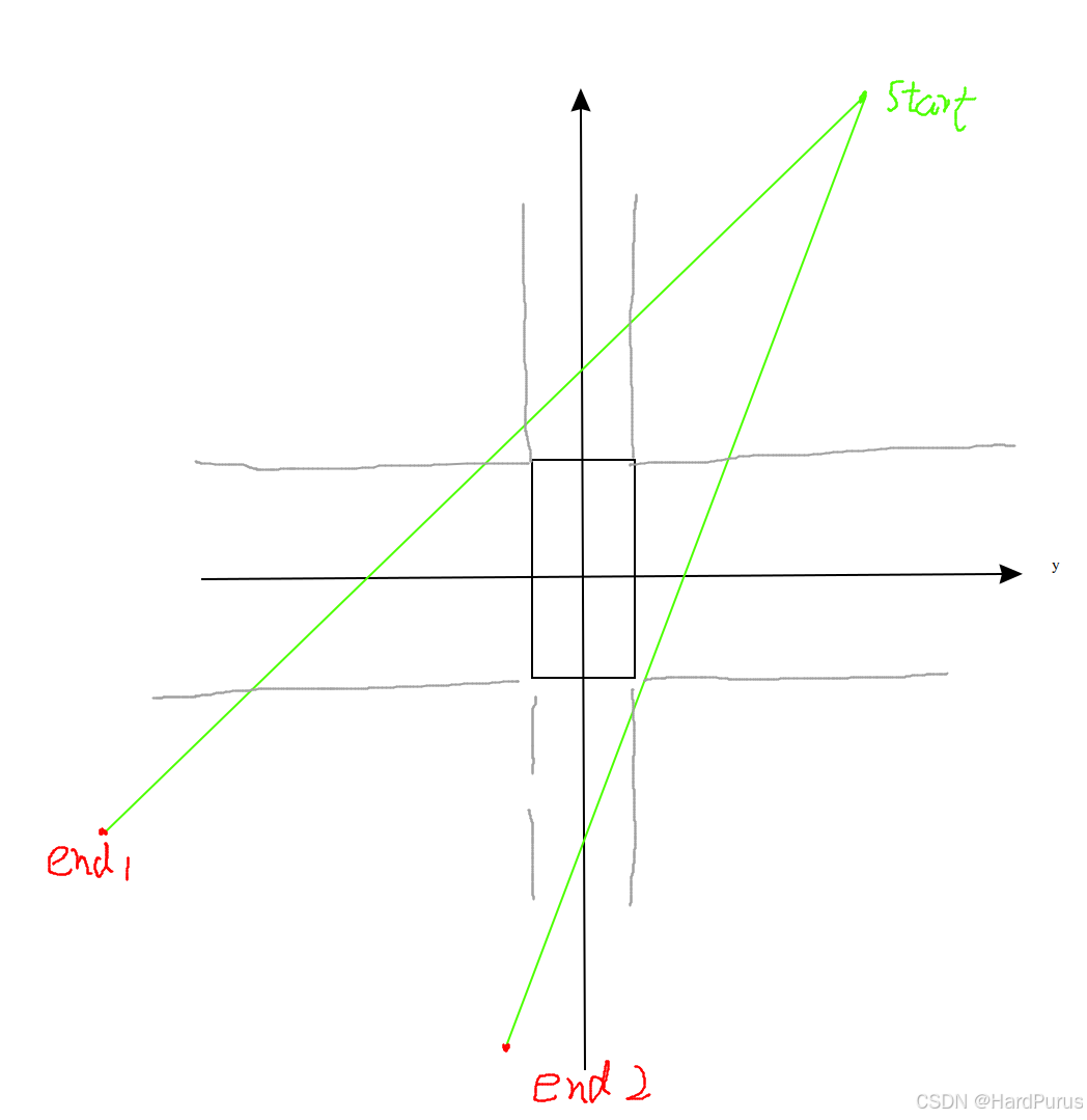
PtSegDistance函数
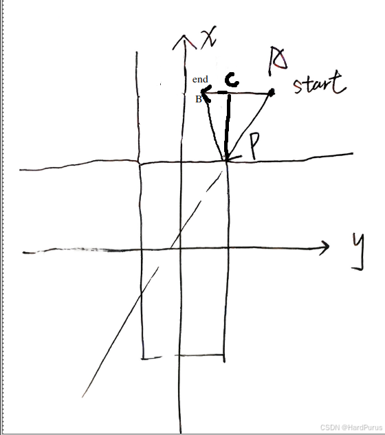
(x0,y0):\vec{AP}
(dx,dy):\vec{AB}
proj:\vec{AP}在\vec{AB}带符号的投影长度(点积)
  if (proj <= 0.0) {
    return hypot(x0, y0);
  }
若投影点在A点右侧,则segment与box间距离为P到A的长度
  if (proj >= length * length) {
    return hypot(x0 - dx, y0 - dy);
  }
若投影点超出了segment的长度,则segment与box间距离为P到B的长度
std::abs(x0 * dy - y0 * dx) / length;
若投影点在AB上,则segment与box间距离为P到C的长度
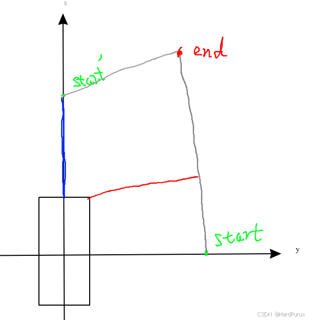
前提:segment的start位置在红色区域
case 4:若segment的end位置在红色区域
case 3:若segment的end位置在橙色区域,若(x1 > x2) ? (x2 - box_x),segment与box间的距离为蓝色线段距离,否则通过PtSegDistance计算segment与box的距离
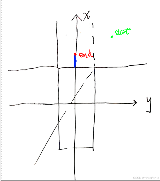
case 2:若segment的end位置在灰色区域,若end在end1位置则box使用角点1计算到segment的距离,若end在end2位置则box使用角点2计算segment的距离.
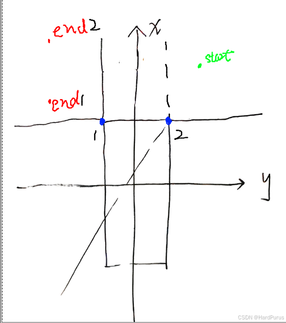
case -1:若segment的end位置在粉色区域,若end位置在end2,\vec{Aend2} \times\vec{AC} < 0,说明segment与box无交集,按正常计算方式计算距离.
若end位置在end1,\vec{Aend1} \times\vec{AC} \ge 0,说明segment与box相交了,直接返回距离0.
可以给每个点一个虚拟坐标,然后进行叉乘,验证判断条件
如果想使用右手定则,需要把坐标轴调整回正常笛卡尔坐标系坐标,使用右手定则,逆时针方向表示叉积为正,顺时针表示叉积为负.
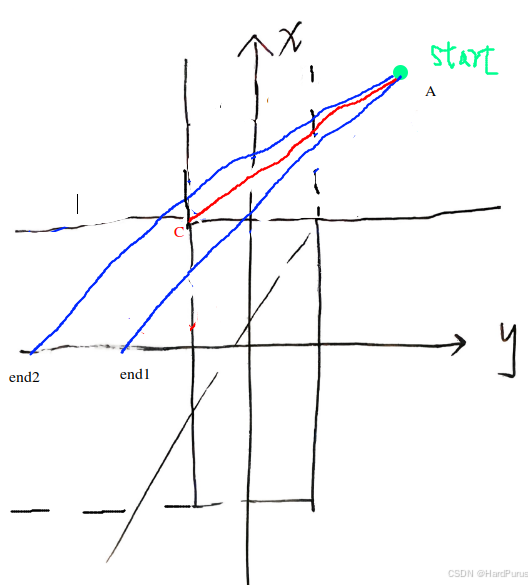
case -4:若segment的end位置在蓝色区域,如果前面看懂了,应该可以看懂下面的图,如果没看懂,就仔细琢磨一下.
还有就是case -1和case -4,因为在前面已经做过对称处理,按正常逻辑是执行不到的.
else {
    switch (gx2 * 3 + gy2) {
      case 4:
        return (x1 < x2) ? (x1 - box_x): PtSegDistance(box_x, box_y, x1, y1, x2, y2,
                                         line_segment.length());
      case 3:
        return std::min(x1, x2) - box_x;
      case 1:
      case -2:
        return CrossProd({x1, y1}, {x2, y2}, {box_x, box_y}) <= 0.0? 0.0
                   : PtSegDistance(box_x, box_y, x1, y1, x2, y2,
                                   line_segment.length());
      case -3:
        return 0.0;
    }
  }
else的逻辑是没有if (gx1 == 1 && gy1 == 1)条件限制的,也就意味着segment起点不在红色区域的情况,但因为做过对称处理,起点只能在橙色和黄色区域
并且当点的x方向值小于y方向的值时,会将整体x值变为大值.
  if (gx1 < gy1 || (gx1 == gy1 && gx2 < gy2)) {
    std::swap(x1, y1);
    std::swap(gx1, gy1);
    std::swap(x2, y2);
    std::swap(gx2, gy2);
    std::swap(box_x, box_y);
  }
x,y值转换这部分存疑
case 4:若segment的end位置在红色区域
return (x1 < x2) ? (x1 - box_x)
      : PtSegDistance(box_x, box_y, x1, y1, x2, y2,line_segment.length());
如果按照代码逻辑,是把起点限定在橙色区域,这块没理解!
case 3:若segment的end位置在橙色区域
如果按照代码逻辑,是把起点限定在橙色区域,这块没理解!
case 1:
case -2:
若segment的end位置在黄色/浅蓝区域
如果按照代码逻辑,是把起点限定在橙色区域,这块没理解!
case -3:若segment的end位置在绿色区域
如果按照代码逻辑,是把起点限定在橙色区域,这块没理解!
从代码逻辑来看,就是把起点限定在了橙色区域
  if (gx1 < gy1 || (gx1 == gy1 && gx2 < gy2)) {
    std::swap(x1, y1);
    std::swap(gx1, gy1);
    std::swap(x2, y2);
    std::swap(gx2, gy2);
    std::swap(box_x, box_y);
  }
如果是因为上面逻辑的话,我的疑问是,因为起点被对称处理后,要么在橙色,要么在黄色,当限定在黄色时,说明起点的gx1 < gy1这个时候无论start和end两个点的x,y都对调了.
然后再去计算距离,我的疑问是下图蓝色线和红色线距离不就有误差了.
这块先存疑吧!!!!!!
到这IsBlockRoad函数就介绍完了.
std::vector<std::pair<STPoint, STPoint>> point_pairs;

...

point_pairs.emplace_back(STPoint(start_s - adc_start_s, 0.0),
                             STPoint(end_s - adc_start_s, 0.0));
    point_pairs.emplace_back(STPoint(start_s - adc_start_s, FLAGS_st_max_t),
                             STPoint(end_s - adc_start_s, FLAGS_st_max_t));
    reference_line_st_boundary_ = STBoundary(point_pairs);
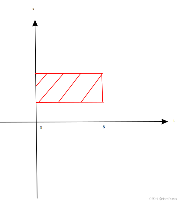
在ST(s-t)图中为一个“会阻塞道路的障碍物”构造一个矩形的STBoundary(时空边界),用于后续速度规划.